Purpose
To investigate the voltage across the capacitor as a function of the frequency in an AC circuit of a resistor and capacitor connected in series.
Objectives
- To calculate the impedance of a RC AC circuit
- To learn the relation between the voltage across each element in an AC circuit of R and C element in series.
- To find out the dependence of the voltage across the C element as a function of the frequency of the input signal
Simulation Used
University of Colorado PhET Circuit Construction Kit AC+DC Circuits.
Definitions
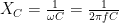
A capacitor in an AC circuit has capacitive reactance of:
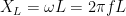
An inductor in an AC circuit has inductive reactance of:
Activity 1. Low Pass Filter (RC-series)
Theory
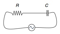
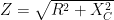
We built a low-pass filter by connecting a resistor and capacitor in series. The impedance of the circuit is:
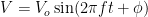
If the current in the circuit is given by 

The maximum voltage across the capacitor is:

The ratio between the two then is given as:

or
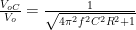
When the frequency is zero the ratio is simply 1. When the frequency becomes very large (

Settings
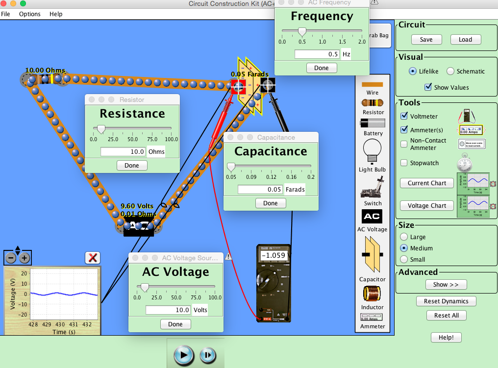
Open the PhET Circuit Construction Kit AC+DC Circuits simulation and construct an RC circuit with a 10-Ohm resistor, 0.05-F capacitor, and a 10.0-V AC source. Connect a Voltage Chart and a Voltmeter across the capacitor. Use the Voltage Chart to see how the voltage changes across the capacitor, and the voltmeter to determine its peak values.
Data and Results
Measure the maximum voltage across the capacitor and calculate the output ratio between it and the maximum voltage in the circuit (10.0 V) for each frequency given below:
| Frequency (Hz) | VC (V) | Output Ratio |
| 0.1 | ||
| 0.2 | ||
| 0.3 | ||
| 0.4 | ||
| 0.5 | ||
| 0.6 | ||
| 0.7 |
In a spreadsheet, plot Output Ratio vs. F (Hz). Does the cutoff frequency from the graph agree with the theoretical value?
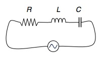
Activity 2. Impedance of RLC series circuit
Theory
When a resistor, inductor, and capacitor are connected in series to an AC source, the impedance of the circuit is:

The amplitude of the current in the circuit is given by:

and it is the largest when the impedance has the smallest value. The frequency at which the impedance is the smallest is:

If the current through and the voltage across the resistor are given by


then the voltage across the inductor will be (leading ahead of the value for the electric current by π/2):

and the voltage across the capacitor will be (lagging behind the value of the electric current by π/2):

In the RLC circuit, the total voltage will be the sum of the voltage across all three elements:
Here φ is the phase difference between the electric current through and the total voltage across the RLC circuit and theoretically it must be equal to:

Experimentally, φ can be found by measuring the value for the voltage across the circuit when the current through is zero. Then 

Settings
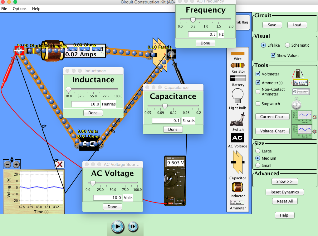
- Open the simulation and connect a 10-Ω resistor, 10-H inductor, and a 0.1-F capacitor in series with an AC source of 10.0 V amplitude and frequency of 0.5 Hz.
- For the given values, calculate the impedance of the circuit and the phase difference between the current and the voltage in the circuit using Eqs. (1) and (5). These are the theoretical values.
- Place an ammeter in series with the RLC elements the measure the current in the circuit. Place a Voltage chart and a Voltmeter across the RLC portion to measure the voltage across.
Data and Results
- Measure the maximum values for the current through and the voltage across the circuit. You might stop the simulation and progress step by step to find the maximum values from the ammeter and the voltmeter.
- The experimental value for the impedance is calculate by using Eq. 2
- When the current through the circuit is zero, determine the voltage across the circuit, V. Calculate the phase difference by using Eq. 6:

Data Table
Record your data in a table where you compare the theoretical with the experimental values:
| R (Ω) | L (H) | C (F) | f (Hz) |
| 10 | 10 | 0.1 | 0.5 |
| Ztheor | Zexp | φtheor | φexp |
Results
Post the results from Activity 1 and 2 electronically on BB.