AC Circuits
Purpose
To build a low pass filter using a capacitor and resistor in series and to investigate how the filter response as a function of the frequency of the input signal.
Objectives
- To learn how to use of a digital oscilloscope
- To calculate the impedance of a AC circuit or a resistor and capacitor in series
- To learn the relation between the voltage across each element in an AC circuit of R and C element in series.
- To find out the dependence of the voltage across the C element as a function of the frequency of the input signal
Equipment
- Digital Oscilloscope Tektronix TDS 2001C
- BK Precision 4010A Function Generator
- Breadboard, resistors and capacitors
- 3 BNC cables, 1 banana-banana plug cable
Definitions
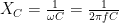
A capacitor in an AC circuit has capacitive reactance of:
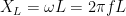
An inductor in an AC circuit has inductive reactance of:
Activity 1. RC Low Pass Filter
Theory
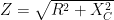
We built a low-pass filter by connecting a resistor and capacitor in series. The impedance of the circuit is:
If the current in the circuit is given by 

The maximum voltage across the capacitor is:

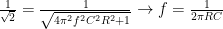
The ratio between the two then is given as:
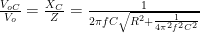
or
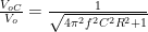
When the frequency is zero the ratio is simply 1. When the frequency becomes very large (
Experimental Setting
Use a 1.0-kΩ resistor and a 0.1-μF capacitor to connect them in series to the Function Generator and and turn the power on.

Measurements and Data
Calculate the theoretical cutoff frequency using Eq. 6.
Using the oscilloscope, measure the frequency for which the max. voltage across the capacitor is half the value of the max. voltage across the RC circuit.
Compare the two values.
Activity 2. RL High-Pass Filter
Theory
We built a high-pass filter by connecting a resistor and inductor in series. The impedance of the circuit is:

If the current in the circuit is given by
The maximum voltage across the inductor is:

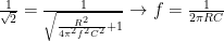
The ratio between the two then is given as:
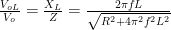
or

When the frequency is zero the ratio is simply 1. When the frequency becomes very large (
Activity 3. The impedance of RLC series circuit