Purpose
To map the equipotential lines produced by two parallel plate and two circular electrodes.
Objectives
- To learn how to use multimeters as voltmeters
- To learn how the equipotential lines look that are produced by two parallel plate electrodes
- To learn how the equipotential lines look that are produced by two circular electrodes
Equipment
- Board with resistance paper attached to it
- Multimeter
- Power supply and electric wires
Pre-lab activities
Go to the Multimeter Page and read through all the sections of the Overview Page: how multimeters work, what symbols on the front are, how you connect them, etc.
If you wish to have some hands-on experience with the multimeters before our lab, you can visit the Alexandria Science Resource Center (AA 415) where you can find the multimeters that are used in physics.
Theory
The equipotential lines are lines that correspond to the same value of the electric potential.
Experimental Set-up
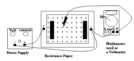
Connect the resistance paper board to the power supply. Set the multimeter to measure volts and connect its COM input to the ground of the power supply. Turn the power supply to 10 V. Using the voltmeter probe, determine the 2, 4, 6, and 8 V lines for (a) parallel plate electrodes and (b) circular electrodes.
Results
Draw the equipotential lines on a separate sheet of paper.
Question. Can you determine the electric field lines from the equipotential lines?